Circuit FAIL
 First- the good news.
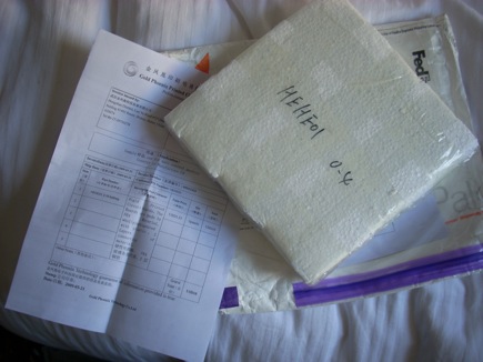
The circuit boards came in from Gold Phonenix, it really is very easy to order from them, and I am pretty happy with the quality. I first contacted them on March 13th (Friday), asking for quote confirmation for a 155 in^2 “Special Price” order, including the gerbers in a .zip file and my location (California). I was given a quote on the 15th (Sunday). I sent the money via PayPal, with my shipping address and the name of my .zip file. I was notified that the order was processed on the 16th (Monday). A shipping notice with tracking number was sent on the 23rd (the next Monday), and I recieved the boards this morning. That’s roughly 12 days.
 The boards look quite good, all the traces and through plated holes stand up to visual inspection. The silkscreen is not very well alligned, and has minor smudging in a couple places.
 I was quoted for 2 8″x8″ panels, with 4 boards each, and recieved 3, for a total of 12 boards, 168.75 in^2. This is in line with other reports I have read of GoldPhonenix delivering more than you might expect. Fine with me! These boards ended up costing about $10 each, $.71 per square inch. Really good deal.
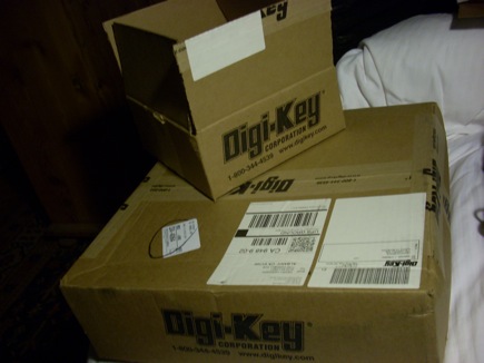
My order of parts from Digi-Key arrived over the weekend. It has now taken the record of biggest Digi-Key box yet from the prototype parts shipment.
 Better yet, I managed to order all the parts I need! Planning pays off.
 So far so good, the power supply section of the board works just fine-
 and the ICSP works just fine
 The power transistor footprints look good, I picked up some 3/8″ long 4-40 machine screws and nuts- looks pro
So, where’s the dramatic tension? Why is this post named “FAIL”? Because I screwed up the circuit- take a good look at that first image, DUH, I swapped the connections to C and E. It’s so clear now. Oh well, I can live with a little re-work. Gives it character. Everything else seems to work well. I’ll fix that, and fix my minor screwup with the silkscreen labels of the faston terminals- CONN_1, CONN_1, CONN_1… is not very descriptive. I thought I had fixed that- KiCad un-fixed it when I reread the netlist. CONN_1 is the default value of that schematic element, and by default it is not printed in the schematic- so you have to double click on the schematic element, go to “Fields” then select “Value” to change it. You can change the text in pcbnew (be sure you change the value, not the reference), but it will revert to whatever Value is in the netlist if you read the netlist in.
I also replaced the current limit resistors on all the LEDs with 470ohm instead of 220ohm, except for the (blue) power LED.
I think we can make this work.