The Alien Torch
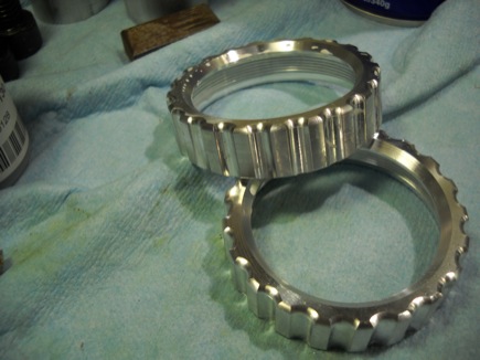
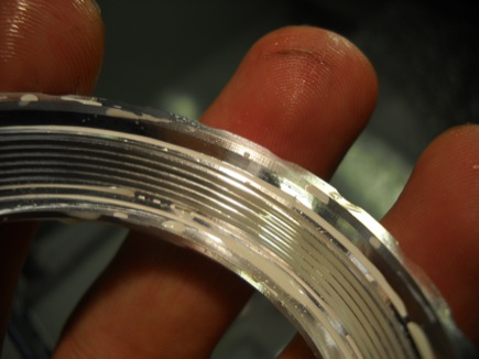
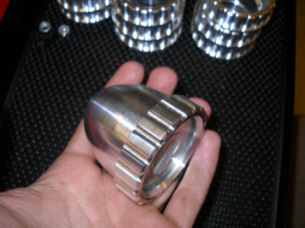
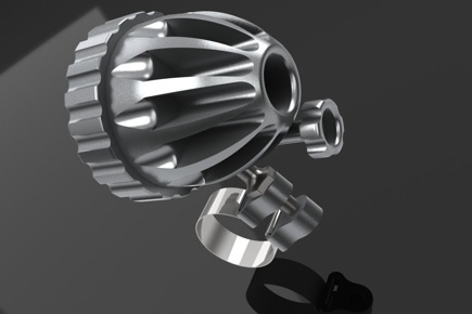
The alien torch- finally documented! After practically a year, I’ve finally put up the photos/descriptions I was planning for the Alien Torch! What is the alien torch? You may have seen the thumbnail on the homepage recently– Now, for your visual pleasure, check out all the photos here!
This is my first try at the “static project page” which the re-design of the site several months ago was geared towards- let me know what you think!
In: Art and Design, Machining
BAS Alternator- Part 2
The Plot Thickens…
I worked on the alternator again this morning, I decided it was time to remove the pulley and get the case open, one way or another. I beat on the pulley with a hammer some more, put some penetrating oil on it, pried at it, and just as I was about to fire up the angle grinder to destructively remove it I decided I’d give it a few more concerted whacks with the hammer, just since I was going to destroy it anyways… and pop! the tapered bushing flew out and the pulley was free.
First impression: This is not like any other alternator I’ve seen before…
Let’s see what’s going on here.
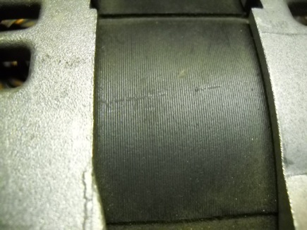
Stator looks pretty normal, looks like it’s wound with the same wire in the same method as a regular alternator.
The rotor, on the other hand… first off it’s got eight pole pairs, as opposed to the usual six. Secondly… what’s that in between the claw teeth?
Little ferrite bar magnets, in fact!!
Now, a couple comparison photos, comparing a standard GM parts bin ’90s Delco Remy alternator (I believe it was used on a northstar cadillac) to the BAS alternator. Stators:
Rotors:
Notable, aside from the different number of pole pairs and the magnets are the lesser gaps between the claw teeth, and the smaller angle of taper- the BAS alternator teeth are closer to rectangular than the the standard teeth are. I don’t know what this all means, but I would hazard a guess that these changes will improve the efficiency of the machine.
Coooool! Now I need to come up with a commutation sensor and controller, and some way to get a sprocket on the shaft. I’m glad I did not have to destroy the original pulley. Given the knowledge that it’s running 8 pole pairs the Austria Microsystems AS5134 won’t work (6 pairs max), maybe the CUI AMT303 is still an option.
In: Electric Vehicles
GM BAS Alternator
A little background: GM has two lines of hybrid vehicles, large full size truck “Two Mode” systems, which are a little bit like a Prius torque-split bred with an automated manual, with a few extra clutches and planetary sets thrown in for good measure, and the decidedly underwhelming “BAS” belt-alternator-starter mild hybrid/start-stop system. The BAS system was found on the “Green Line” Saturn Vue and Aura, as well as on the Chevrolet Malibu Hybrid, starting in 2007. A new higher powered system has been announced for 2012. The Malibu hybrid did not sell well and was soon made available only to fleet sales.
The system uses a motor/generator packaged very similarly to a standard alternator, with a special high-tension 7-rib ribbed V belt drive to the crankshaft. A standard starter motor is used to turn over the engine when cold, once the system is active the a modest amount of regen and assist, as well as start/stop operation is run through the BAS unit. The most reasonable figures I could find for regen/assist capability were 5kw/2kw, respectively. The system runs with a 36V trunk mounted NiMh battery.
I have been hunting for a BAS Alternator for a while to see if it might be suitable for a installation on an EV, most likely a “big bicycle”- in the 100 lb/45mph range. I finally got an opportunity to snag one in my price range- I immediately went about dis-assembling it to try to determine if it is even worth putting on a bike- Spoiler: it’s got some immediately visible plusses and minuses, but I think it’s worth a try.
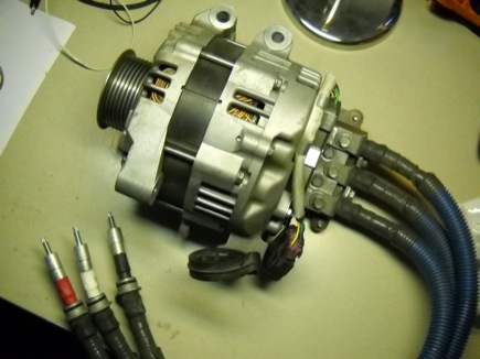
The BAS Alternator in the flesh. This example is from a 2009 Malibu Hybrid. I purchased it from an auto dismantler.
The rear-cover of the unit.
Phase wire junction box. The phase cables appear to be somewhere in the #2-#6 region. The wiring is very nice, all the connections are pretty robustly weather-sealed.
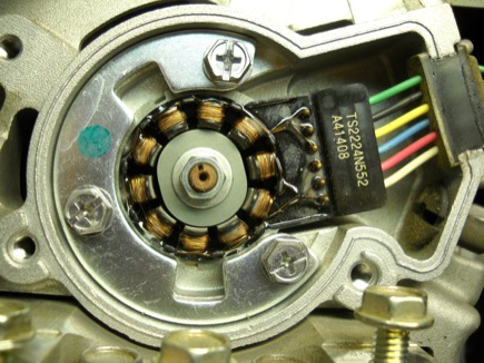
Position encoder, under the rear cover. I would hazard a guess that it’s a type of resolver or sin/cos style sensor, but I am not sure really.
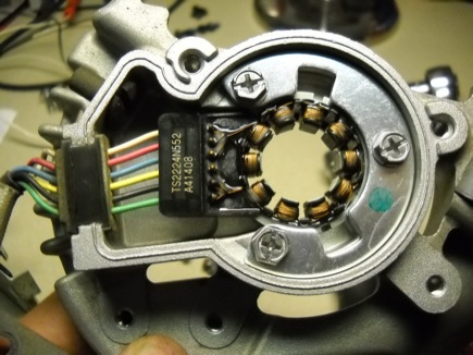
The rear cover plate comes right off the alternator, carrying the sensor with it.
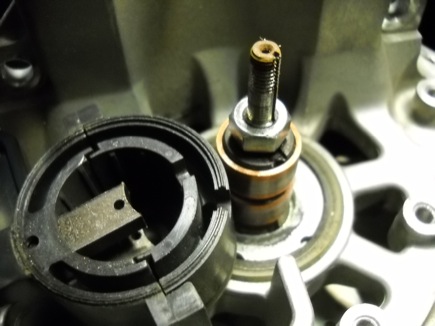
Revealing… BRUSHES. Dang! I was really hoping this might be a PM machine. Oh well, all is not necessarily lost. The sep-ex rotor is only one of the several factors that generally make alternators non-optimal motors, hopefully some of the other important factors are indeed better on this BAS alternator.
The laminations look really good- nice tall stack of what I guestimated at .3mm thick lams. Lams that thin aren’t cheap and may indicate that some cost and effort was made toward making this alternator more efficient than the average, which has lams more around 1mm thick.
That’s where my dissection finished- most alternators use the nut on the end of the shaft to retain the pulley- the torque on the pulley is always tending to tighten the nut- since the torque on the BAS alternator goes both ways, for regen and assist they clearly needed a more robust method of attaching the pulley- prompting the use of a tapered bushing, which unfortunately has no jacking screw holes or other obvious way to get it apart. I’m a bit stymied about what to do next. I’ve come up with three general options: Use the 7 rib pulley as is, onto a jackshaft for dual reduction, or direct. Hacking it off with a grinder, then figuring out something to replace it with, whether that be another taper bushing or keyed connection. Or, lastly maybe machining the pulley in situ for a flange that I can mount a sprocket on. Unfortunately I wasn’t able to get the case split apart with that pulley on there- so I was not able to get a look at the rotor or stator more clearly.
So that’s where this investigation lies for now. I have an idea in the back of my mind of building a bike to go around this motor and racing it later in October… but that idea’s far from baked yet. I definitely think the BAS unit has some potential worth exploring.
CNC Bike Headlight – Part 3
Thinking about a proper name for this project- “Mega Beaminator”… what do you think?
Yesterday I finished running the 2nd operation on the “nose ring” lens retainer piece- as I mentioned last time I opened up the ID behind the threads just enough to make slight pressure on an o-ring dropped into the thread relief groove on the “light body” part, and added a 20 degree chamfer to ease the compression of that o-ring. Since school has started up at Laney it was top priority to get that part out of the machine, so that the CNC class can setup the machine.
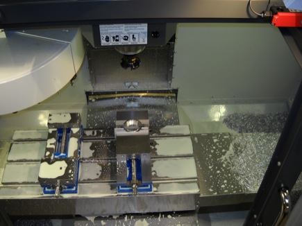
I made it back to Bob’s house a couple weeks previous to finish machining the operation I had set up in his Matsuura, the inside cavity in the “Light body”. That went generally without incident, aside from breaking a 4-40 tap in the very first piece. It was clear why that had happened- inadequate coolant, bad tool-holder, non-optimal type of tap- after switching from a spiral flute tap in a drill chuck to a roll-form tap in a tap-holder the rest of the parts went perfectly without incident.
So now, just two more mill operations on the “light body” piece, then a simple 2 operation part- the LED mounting sub-plate that fits inside the “light body” – I mentioned last time that I was planning a handlebar mounting bracket based on o-rings or zip ties or hose clamps- I’m thinking that would be a good application for trying out 3d printing, either on Laney College’s Dimension printer, or through Shapeways (or both!). That way I can design a really goofy part without any concern for how many fixturing setups and special tools it would require to machine it. And making new design iterations if it doesn’t work at first will be much easier. That’ll be a fun challenge once all the machining is done.
Boosted/Busted
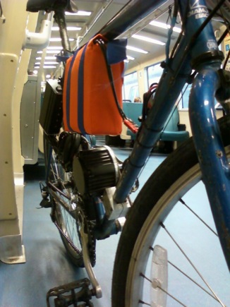
Since I last posted about running the Bike on a 12S LiPo setup (44.4 V Nom.) I did some work on the setup- I sewed up a bag for the four 6s packs with padding, and took it on my work commute last Wednesday. Things went well in the morning- cut my biking time in half- with average speed of 19+ mph, and only 3.6 AH used on the 10AH pack. I avoided flat tires and the extremely unlikely but terrifying scenario of a battery fire on BART.
I charged the pack at work using the Hyperion balance charger and on a 24VDC supply I was able to borrow from work. All was well.
Then, just before leaving work for the BART station- disaster! As a coworker was riding it around the parking lot it began making horrible scraping noises- it was clear that something in the front motor pulley had let go causing the pulley to scrape against the belt guard plate- something that had never happened before. There should be absolutely no movement in that pulley- I decided that I would investigate later- removed the belt and pedaled back to BART. What a disappointment!
On Saturday I finally got a chance to autopsy the motor shaft/shaft adapter situation- after blasting it with a propane torch to loosen the bearing locker I filled it with last time I put it together I was able to pull the shaft adapter apart- surprise!
The motor shaft sheared off right where it necks down to 8mm.- but also down into the cross-drill. I figure the side loading on the long shaft adapter, combined with the slight play inside it, must have caused the shaft to fatigue and break. The fact this happened after doubling the motor power input can’t have hurt either.
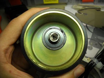
I decided to pull the rotor out to investigate how difficult shaft replacement would be.
It looks like the shaft is swedged into the rotor bell- the way that occurs to me to replace it would be boring a hole in the bottom of the rotor, with a bolt circle, then making up a shaft with a flange that fits the bored hole and bolt circle. It’d be nice to upgrade to a standard 1/2″ or 5/8″ shaft, but the bearings are 26 mm OD metric and there’s not really much meat on the bearing pockets to enlarge them. It’s possible to get smaller profile 26mm OD bearings with much larger inner dimensions, I’m not sure really if that’s an acceptable tradeoff- I’ll have to get some advise about that.
So, it comes down a question- is it worth it to rebuild?
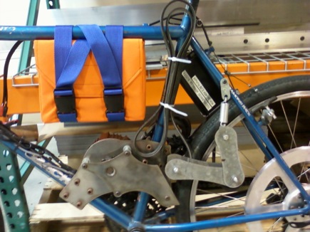
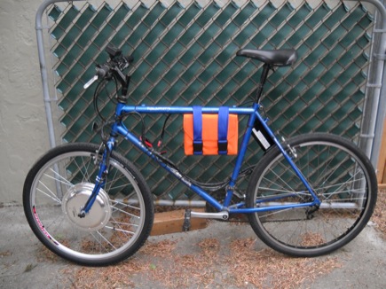
In the interest of having a working ebike, and out of curiosity I did a little re-configure on the bike and installed the front-hub 9 Continent direct-drive motor I purchased from ebikes.ca a little while back-
Taking it on the “standard test-ride circuit” revealed some interesting aspects of the performance, useful to compare with the old Hi-Kol/Poly-V drive. Power and torque were quite similar, the cycle analyst recorded peak amperage of 10A lower with the 9C motor. The top no-load speed is about 37mph, wheras it was likely north of 40 with the Hi-Kol, my estimate, since the speed sensor is on the front. In my short testing I believe the efficiency of the 9C motor is better, but not by too much. Of course that depends entirely also on how you use the throttle. The 9C motor is quieter, but still makes a fair amount of noise.
Most notable is the difference in handling. I’m just going to say my initial assesment- heavy direct-drive hub motors suck when used in the front fork of a bike. The unsprung weight is distinctly noticeable and the handling is plagued by “torque steer” like effects. I’m concerned for the dropouts with the copious torque the motor is generating as well. I’d like to set a lower amperage limit, or get a smaller controller on it. I think that’d make it handle less dangerously as well.
If you keep it generally modest and smooth on the throttle it behaves well enough though, and the torquey acceleration is pretty fun, definitely no worse than the old setup, with the suspected increased efficiency as well it’s a pretty good first impression.
I’m still not a real fan of the hub motor- there’s just something wrong seeming to me about putting a heavy motor in the wheel hub, particularly on a suspended bike- but I’ll ride this for a little while as I consider where to go next- I don’t expect it to convince me to invest more in hub motors, but it has already made me reconsider whether the poly-V drive is the best option for efficiency and flexibility.
Ditch the Lead
I finally took the plunge on some hobby airplane-style Lithium battery parts for the ebike- it’s needed it for so long!
Goodies! That’s 4x 6x Zippy 30 C 5AH packs, 24 Headway 38120 cells, a Hyperion EOS1420i Net3 charger and a Revolectrix Cellpro Powerlab8 charger, as well as a new Cycle Analyst and a nice bag of Digikey stuff (MCE-stars and lenses for the HeadLight)
After hooking up Powerpoles all around and throwing a quick charge on a pair of Zippys-
I gaffa-taped them to the bike and took a late night test ride. What an amazing upgrade! Losing 45 Lbs and gaining 10+ volts makes an amazing difference. Even these cheap LiPos are incredibly stiff (compared to lead, at least) and deliver amazing power. I like the Hyperion charger alright and I love the Powerlab- if only it could do 12s- the design is otherwise top-notch in every way- at least from my tiny amount of experience so far. The regenerative discharge is also a super neat feature.
I observed a no-pedaling top speed of 30.5 mph, while pulling about 1500W. Much greater efficiency can be had from slower speeds. I need to figure out how to set up cruise control for easier economy-riding. I think once I get these batteries attached to the bike in a more legit fashion I will definitely be good to try taking it on BART for the work commute. Can’t wait!
CNC Bike Headlight- Pt. 2
In between busy weeks at work and a week off in Ohio attending to family stuff I’ve been moving along with the bike headlight, making progress but coming home too tired to post anything. An update is in store.
First I finished running out the first operation on the “light body” part on the Hass SL10 CNC lathe.
I took a video of the cycle but I need to do some serious editing to it, mostly just looks like coolant splattering on the lens. There are good parts that are fun to watch, but mostly just a sea of blue foam.
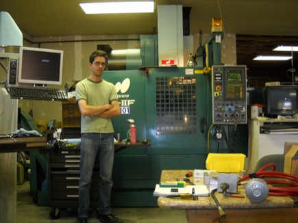
Next I was starting to feel unsure about the pace things were progressing at- feeling stalled and frustrated by my limited access to the community college shop during the summer- so I prevailed upon my supervisor/teacher at work who has a machine shop at home- he took home his favorite set of machines after owning a CNC machine shop for many years. He generously allowed me to come out to his place and work on the part in his machine- a Matsuura RA-IIF two pallet mill.
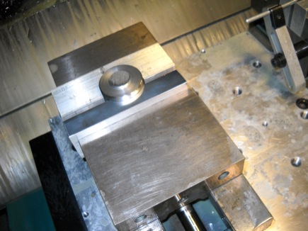
I spent most of the day prepping aluminum vise jaws, planning and programming, as well as familiarizing myself with Bob’s programming workflow and Yaznac machine control. The Matsuura, while not brand new has an extraordinarily high quality feel to it- tight, rigid, accurate- but somehow most strikingly quiet and smooth. I really enjoyed operating it and look forward to finishing out the light body piece on it in the next couple weeks.
Finally last week I was able to spend two nights at the community college where I turned my attention to the “nose ring” threaded lens-retainer that screws onto the front of the “light body”.
This part was made from the material left in the jaws of the lathe after turning the “light body”- the lathe spindle drawtube was too small to fit the stock, so each piece is left with a slug of material held in the chuck. I purposely bought oversize material for the light body so that that extra material could be used to make the “nose ring” pieces.
I set up for this part in one of the College’s two brand new Hass VF-2 3 axis mills, fully furnished with excellent brand new Sandvik tooling.
I like the new Hass machine also- the Hass control has a lot of really convenient user-friendly features, and the machines seem to be adequately rigid and powerful. They’ve certainly got a fast rapid speed, for such a small travel machine! I’m not a big fan of the carousel style toolchanger, particularly without a chip conveyor- it is dangerous to scoop chips out of the machine with that array of razor sharp tools just above your head. I thread milled the ID thread inside the “nose ring” using a Coromill 327 interchangable-insert grooving and threading tool, which did an awesome job- finish is excellent. It’s a pretty spiffy tool.
I ordered all the endmills I’ll need to finish out the Lightbody part- then it’s just running them and the “nose rings” out, and making a couple other parts. I have been working on redesigning the handlebar mounting scheme to use a rubber O-ring as a elastic strap, like many commercial bikelights do- ditching my previous plan with the ball-and-socket system. I’ve also been thinking about slightly tweaking the “nose ring” design so that an oring can be placed in the thread relief groove in the light body and interface with a smooth diameter on the “nose ring” to give enough friction at the end of the thread to prevent the ring from working loose with vibration, similar to the way the O-rings are used on mag-lights and many other flashlights. I just need to dial in that diameter, and maybe add a more generous chamfer to help the O-ring seat.
Spendy stash of solid carbide tooling. I shouldn’t have bought multiples of everything- it’s aluminum… it’s pretty unlikely I’m going to break a tool, and no chance I’ll wear one out in 20 parts… but I’ve gotten used to buying extras for work.
Sweet MA Ford 3 Flute .250 diameter, 1.125 LOC Aluminum cutting endmill- just right for cutting out the fins in the back of the light-body.
More Lead for More Speed
In an impulsive move the day before the Refuel event at Laguna Seca back on June 26th, I decided to add another 20AH SLA battery to the  Poly-V bike, and swap the controller out for an Ebikes.ca “40 A Infineon” controller I bought a while back for another bike. I was curious to see how it would ride on 36 volts, I thought it might be fun. After wiring up my throttle and hall sensors to the Hi-Kol motor and Magura throttle on the bike I tested the controller with the third battery in a backpack, after proving that it worked I set about mounting yet another lead brick on the frame.
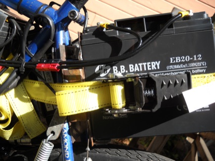
I came up with this location between the rear wheel and the seat-post. A pair of plates with some steel tube allows clearance for the cantilever brake, and a ratchet strap ties it all together. I love ratchet straps- I think they’re very close in usefulness to zip ties in throwing together stuff quickly (as you can see, this bike employs both, successfully)
It’s quite rigid and sturdy.
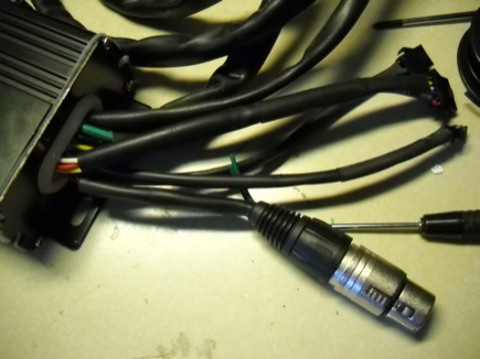
I hadn’t ever used a china BLDC ebike controller (Infineon, crystalyte, etc) before so I didn’t know what to expect- it’s pretty straightforward and worked fine out of the box. I got lucky and got my commutation sensor connections right on the first try- I made a small adapter to connect the JST connector on the controller to the Minifit Jr connector I have on the Hi-Kol motor. I installed a 3 pin XLR connector on the throttle connection to match the hardware on the bike. I don’t really like the feel of the JST connectors. I figure it’s worth a few dollars to run nicer connectors.
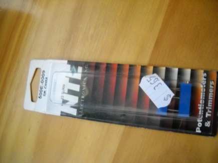
The Magura throttle is a 5k potentiometer type throttle and the controller is set up to run a 1-4V hall throttle- unfortunately the controller was also programmed to cut out entirely when a throttle signal much higher than 4V is applied, which causes an annoying dead spot at the top of the throttle. I solved this problem, along with the large dead spot at the bottom of the throttle by applying a 5k 10 turn potentiometer in series with the top and bottom throttle taps.
The good news is that the bike is significantly faster and fun to ride- it hauls at about 26 on the flat with no pedaling, as opposed to about 19 before. The bad news is that it’s even heavier and significantly less efficient. Back EMF used to limit the top speed nicely to about 20, pulling only about 300-400 watts cruising at that speed (somewhere around 20 wh/mi). While the current begins to taper back at steady state full throttle cruising with this new setup it’s not as much- it draws about 800 watts now. This of course destroys the wh/mi figure, as well as compounding battery sag and peukert effects.
So basically, it’s pretty much ruined. But faster.
In other news I took apart a small 5spd transaxle this morning, because I had it and I was curious- I am also interested in the fesability of using a couple of the gear clusters to make a two or three speed box for a electric mega-bicycle or something. For now I will just hold onto these parts and think about it a bit. While starting with these parts should be easier than cutting helical gears from scratch for a gearbox it most definitely won’t be easy to build something up. Taking stuff apart is always fun if for nothing else to admire the engineering that went in to it.
CNC Bike Headlight – Pt. 1
In order to take advantage of my access to the Laney College CNC machine shop over the summer while there are no classes in session I designed a bike headlight to be made out of Aluminum, in collaboration with my electrical engineer friend Cuyler. He’s already designed a CC/CV boost drive/BMS circuit for a 2S Lithium battery pack driven, dual MC-E light- but didn’t have a light to build it in. I thought I could fill that void, while making a really interesting design and machining challenge.
The design incorporates mounting, heatsinking and weather protection for 2x “star” style LEDs, and <25mm optics.
I’ve been working in the shop two nights a week for the last several weeks, so far working on the NC-lathe cut blank for the main light body. I’m expecting things to pick up once I get on the mill, I’m a lot more practiced with set up and programming for it. Last night I finally got the first lathe operation dialed in, with size and finish tolerances all checking out OK. I was unable to find a positive CNMG432 insert in the shop that might have been able to curl and break the chip during the finishing of the OD- I was having trouble with stringy chips wrapping around the part and scarring it. I have it set now to take a “rough finish” cut at .01 feed per rev, then take a .002 deep final finish cut at .002/rev- the chips become long and stringy but aren’t substantial enough to mark the part in the presence of the flood coolant.
I consider that operation “ready to go” now and have about 12 blanks precut- next time I get a chance I’ll run those parts and start setting up soft-jaws in the mill for the 3 remaining mill operations on that part.
There’s at least two operations for each of the seven parts in the assembly-I need to make some quicker progress if I hope to finish before school starts! But at least it’s most all aluminum, which should be fast and easy once I get on the mill where I’m comfortable.
In: Machining · Tagged with: cnc, headlight
July 2011 Site Overhaul
Go ahead- check it out!
I’ve reworked the site to remove some focus from the blog, in order to make it less formal and hopefully increase posting volume to keep it more current. Shorter, more frequent updates. The main meat of the site will be static pages describing my more complete or noteworthy projects, which will (soon) appear on the homepage.
As well a jaunty new graphic layout- out with monochromatic, in with color- I’m not 100% on the color scheme but it’s trivial to change it. It’s sort of pool-noodle flavored right now, which I guess is fine now that the weather is nice.
I did some word-press hacking to get the content where I wanted it, which while not completely straightforward wasn’t too tough once I found some good resources on “The Loop” and WP_Query. Most importantly I haven’t seemed to break too much stuff in the process. The site is mostly just simplified. Hopefully there’s adequate navigation functionality. If you have any input don’t hesitate to comment or email!
In: Art and Design, Life and Times, Projects


