Battery regulator- part 2

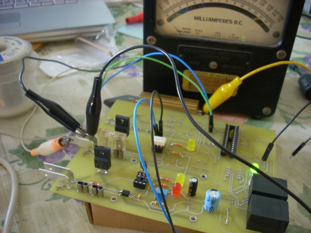
I continued troubleshooting the board yesterday, and came to a few conclusions- The gain of the power transistor is indeed high enough to be driven directly from the optocoupler. In order to get the C-E voltage drop nice and low (.35 v or less) I am driving the base with about 20 ma- it’s definitely saturated. The optocouplers I ordered have CTR 40-80%, so as it is right now, it’s a bit of a balancing act with keeping the OC pulling less than ~30 ma from the AVR pin while maintaining enough C-E current to keep the power transistor saturated. I think next time I order parts I will order higher CTR optocouplers (there are some better ones in the same series of parts) and maybe tweak the resistor values just for a little headroom.
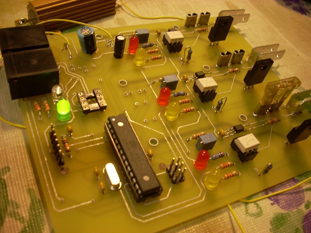
After having gotten that squared away (whew!) I took a quick trip to Fry’s in Sacramento (got very lost on the way. Why are there two different freeways with such similar names?? I80 and Business 80?) to pick up some new resistors for the power transistor base and the optocoupler LED. Was also able to find pinheaders (Yuss!) and a 5v linear regulator. Having all the parts, I finished populating the board.

(Note the upright metal film resistors placed in the TO-92 footprints)
Looks pretty good, right? Well then I couldn’t connect to the microcontroller via my USBTiny and ICSP header. Frustrating. I thought about it overnight and then earlier this morning I confirmed my suspicion that one of the ICSP pins (MOSI in fact) was also being used to drive one of my optocouplers- I assume that was putting enough of a load on the pin that the ICSP was unable to connect.
So, I would say that most of the kinks have been worked out of this hardware! I’m going to take some time now to fix up the schematic and do a little bit more trace reworking on the board so that it’ll reflect the schematic changes. A note- in KiCad eeschema, using wire labels is useful- but if you have labels like Sense 1, Sense 2, Sense 3, they will all be assumed to join together. So don’t include those spaces- I didn’t get this when I was first trying to layout the board so I made wires in the schematic between everything- messy. I’ve fixed it now.