Battery Regulator- part 4
I finished testing the battery regulator board over the last two days, as I planned I did a full-current “burn” test and tested the MCP2551 (CAN transciever) based communications circuit. Things went mostly according to plan.
I had planned to burn in the power circuit for ~2hrs, but I got all the information I needed in about 15 minutes- the transistor is fine, by my calculations it should be burning no more than 1w (less with higher hfe optocoupler) which the datasheet specifies is OK without a heatsink up to ambient temperatures of 40-60 C. So, I will make thermal pads and bolt the TO-220 pads to the board, I don’t think a heatsink is necesesary.
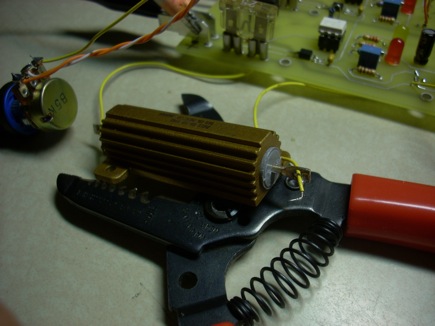
The power resistor on the other hand didn’t fare so well. Just because a power transistor is rated “50w” doesn’t mean it can take a power close to that limit for a sustained amount of time without any thermal considerations. That resistor got crazy hot. 33 watts is a lot of power when it’s all going to heat in such a small area. The anodizing changed colors, the plastic plugs at the ends of the resistor expanded outwards and the solder melted causing the wires to slide around.

I cut the power when I noticed this, once it cooled down again the plastic plugs retracted slightly, but you wouldn’t mistake it for new- and the anodized surface is still a little darker than new resistors. It still reads an acceptable resistance though, so I’m not going to toss it.
When revising the schematic earlier I decided to nix the “Fan” output transistor, which after seeing this I have decided to add back in. I think if I mount the resistors on some aluminum plate and use some forced air everything should be OK.
About the MCP2551 CAN transciever, which I added to the schematic as an easy robust way to implement an EVILbus style communication bus (BatBuss) is a complex little guy- read that datasheet closely. I assumed it wouldn’t care how slow the baud rate on the bus was, so I could use it for even DC signals- that’s not the case though.
1.5 TXD Permanent Dominant
Detection
If the MCP2551 detects an extended low state on the
TXD input, it will disable the CANH and CANL output
drivers in order to prevent the corruption of data on the
CAN bus. The drivers are disabled if TXD is low for
more than 1.25ms (minimum). This implies a
maximum bit time of 62.5μs (16kb/s bus rate),
allowing up to 20 consecutive transmitted dominant bits
during a multiple bit error and error frame scenario. The
drivers remain disabled as long as TXD remains low. A
rising edge on TXD will reset the timer logic and enable
the CANH and CANL output drivers.
When I used another MCP2551 to check the onboard one by making a little sketch to toggle the “TX” pin every couple of seconds I got no output on the second transciever. When I set the sketch to toggle with 2ms cycle delay (effectively probably 300-500 hz) my multimeter read ~2.5v on the output of the second chip. This would idicate a duty cycle of 1/2 and is enough to make me think the chip is working right. This means my bit-banged “BatBuss” must run at at least 16kb/s- more challenges. At least I can leave that until later.
And voilà – I think I have enough information to redesign the board. When I have finished, and verified correct operation in service I will post the schematic and software, or at least software specifications. I have considered making this a kit also, since I wasn’t able to find these regulators on sale when I was looking, someone else may be interested in skipping this arduous design process!
I have been meaning to publish some of my older projects, as well as to make an about page, put up some links, and change or customize the CSS- look for all that soon.