Battery Regulator- the OTHER part of the project
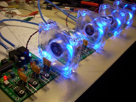
I devised a workable fix for the circuit FAIL previously described and finished assembling a set of four battery regulator boards- their relatively small size belies that they have a LOT of parts on them! They are a pretty involved assembly project!

I haven’t tested everything about every board, but as far as I can tell, so far everything seems to be working as it should.

What’s Next?
Let’s review the theory of operation of shunt regulators- The charger fast charges (constant voltage) the series string of batteries until a regulator detects that a single battery has reached a voltage setpoint, indicating that it is full. The regulator starts shunting the charging current off that battery. The charger then throttles down to an “absorbtion” rate charge (constant current), and as other batteries fill, their regulators shunt off them too, until every battery has reached the voltage setpoint as detected by the regulators. At that point, the charger enters a float charging mode until it is unplugged from “land” power.
I now have regulators that detect voltage, are able to shunt current and communicate with a master via one serial port of currently undefined protocol and two digital lines that can be pulled low or high by the µC pins. I need a way to instruct the charger to enter the second and third stages of charging. The charger (Manzinita Micro PFC20) has a 6 connector RJ12 port called REGBUS which is designed to allow the charger to work in sync with Manzinita Micro’s Rudman Regs. It’a an analog interface, electrically specified pretty well via the files on this page. There is no specific information or How-To on faking the interface with a microcontroller though- it’s a simple bus though, so I decided to figure it out myself. I have a current clamp meter to monitor the charger’s output, and some potentiometers and RJ12 plugs and wires to generate signals on the REGBUS, I’ll see what happens. I was thinking of picking up a pair of L16 batteries to test with, which I can then integrate into my long neglected solar-electric power system.
I can envision this working one of two ways. Either the charger current response is proportional to the analog signals on the REGBUS, or the current response is preset and the analog signals are used as triggers to move the charger into different preset modes. I hope it’s the latter, so that I can generate the analog signals with a few resistor networks and optocouplers- if it’s the former, I might have to look into digipots or DACs.
No use thinking too much about it before actually doing the testing and figuring out what I’ve actually got to work with here.
In order to make the charging system work without intervention, I need this master to monitor the “Reduce” and “Finish” digital signal lines on my “BatBuss” connector and generate the analog voltages needed by the PFC charger. In future versions, I’d also like to integrate…
- CAN Bus for reporting state and voltages, AH counts and SOC
- battery current sensor, charging current sensor
- Solid state relay switching of AC side of charger for protection or automatic time of day charger on/off switching
- one RGB LED PWM channel for making a Tesla-style “fuel filler light ring”
- data logging
Sounds good, right? For now, I just want to get the batteries charging. Speaking of batteries, mine are on order! Should be arriving Apr. 8!
on April 27, 2009 at 12:27 am
·