Breaking and Fixing the Mars BLDC Brushless Motor
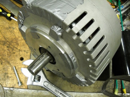
Here’s the short version: Because we are cheap, my friend picked up a Mars “Brushless Etek” BLDC motor from Ebay user “megadan” who has been selling these motors for about half price, with the catch that they are shipped with an odd and difficult to deal with shaft adapter (I’m starting to get used to this reality of cheap and surplus motors)
The first plan we had for removing the shaft sleeve adapter was to cut the end off then hold it in a vise and use a pin to beat the motor shaft out from inside it.
Cutting the end of the adapter was uneventful, so we found a pin and started hammering on the shaft. Seeing no movement we beat on the shaft pretty good. Then I noticed the motor had bound up and wouldn’t spin anymore.
Turned out the hammering caused two magnets to come unattached from the rotor plate. You can see the left magnet in the photo protrudes further from the rotor than the right magnet, it has stuck solidly against the stator. Still no movement in the shaft adapter.
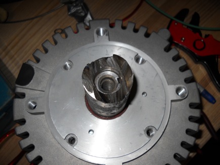
The next day I figured out a better plan for removing the shaft adapter- I used a dremel cutting disc to cut a slot in the sleeve right above the keyway, using the keyway as a relief to cut through the sleeve without cutting into the shaft. The adapter sleeve was held on the shaft purely through friction, no internal keyway. Given the tightness of the fit I would guess it was an interference fit assembled with thermal expansion. After slitting the sleeve I ground out the motor-side of the sleeve in the corner that the dremel cutting disc was unable to reach. I pounded a screwdriver into the slot and the sleeve slid right off. With careful grinding and cutting I managed on only nick the motor case and shaft.
So now, an adapter-less but seized motor. Time to disassemble. But how? There’s just one screw on the outside of the motor that holds it together. Other than that it is held together by the axial magnetic force of the rotor -> stator and the friction fit of the shaft through the rear bearing. There are three metric (M5?) tapped holes in the rear case that can be used to attach some sort of puller rig.
This can only end badly
I bolted the front case to the welding layout table (conveniently spaced holes) and whipped together a plate to bolt to the puller-holes out of some scrap. A 2×4, bottle jack and some bolts and nuts complete the picture. And yes, this is surely a Miller-recommended usage of the Dynasty welder cart.
Spoiler: it ends up working—
Umm, doc? I think we need some more POWAH here
No problem!
Well, there’s your problem right there.
Nothing a whole great smear of epoxy can’t fix
Good as new (that’s not saying much, really)
In order to reassemble the motor I thought more control of the rear case decent would be in order to try to minimize the chance of shaft binding and case snapping. I didn’t know when planning that the force required to press the tailshaft through the rear bearing would be much greater than the magnetic pull between the rotor and stator. So I set up a reverse-puller using three scissor jacks.
Although I ended up whacking the inner bearing race over the shaft using a tube an soft hammer anyways the tri-jack rig was extremely easy to control and secure feeling, I was happy with how it worked even though it was probably not actually necesessary. If you’re attempting this, be sure to keep an eye on the hall sensor wire, pull it back through the grommet as the the motor halves approach.
The freshly rebuilt motor spins freely now and appears to work OK. I didn’t make a mark on the case before pulling it apart so I may have slightly altered the timing (the hall sensors are on the inside of the front case). I don’t feel confident that the motor is as really as good as new, but after seeing the inside of the motor I’m not particularly inspired by the quality of manufacture all around.
Regardless, I think it’ll be a good start for the Kart 🙂
I’ll tidy this up a bit 🙂


on August 22, 2010 at 10:51 pm
·