FE1 Reduction Drive Assembly
Part of the goal with FE1 was to build a dual-drive powertrain, opening up the possibility of active electronic-differential functionality, allowing a torque vectoring system to be developed. During the ’13-’14 year, no torque vectoring system was implemented, but it could be in the future if someone came along willing to put the work in!
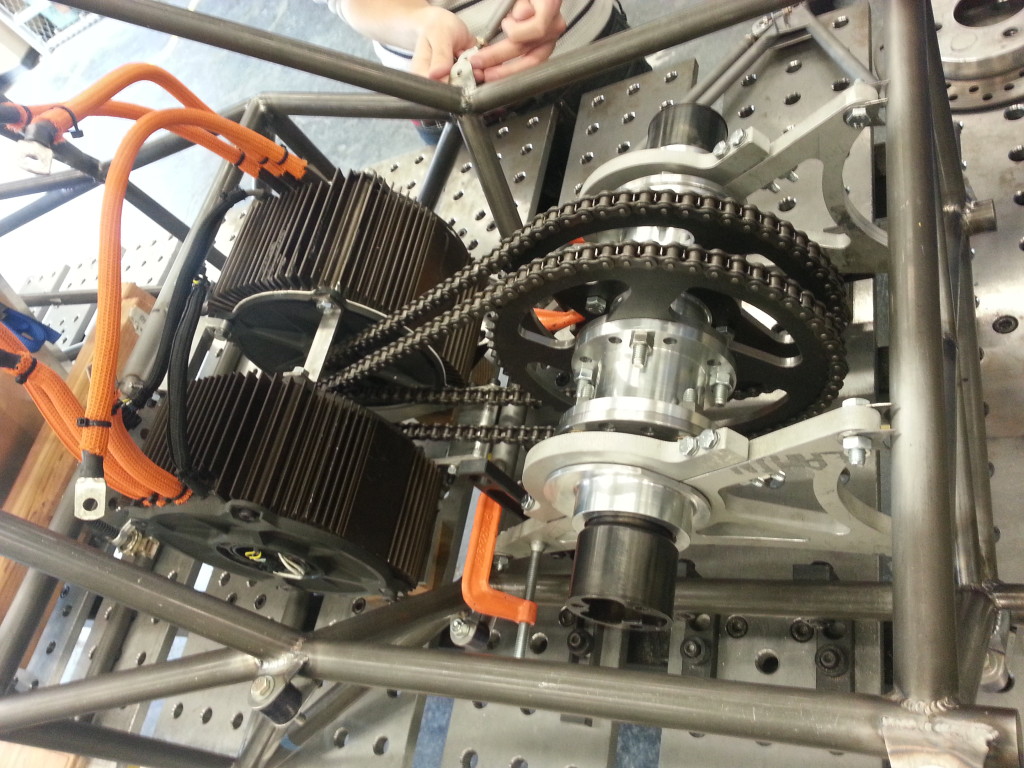
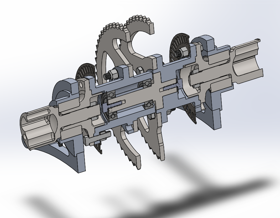
An assembly is placed in the rear of the chassis where the differential would typically go, except it has two large driven sprockets and the two sides are able to turn freely with respect to each other. CV stub-axles are attached to the outsides of the assembly. This “jackshaft” also rides in eccentric carriers to allow chain tension to be adjusted.
In order to allow the two halves of the jackshaft to run independently there is an internal shaft with ball bearings. The shaft is hard-mounted to one of the halves, and runs on bearings in the other half.
Wheel bearings and drive flanges are used for the inboard CVs, allowing easy sourcing of those parts which would be time consuming to machine from scratch. The brackets were water-jet cut, while requiring post-machining for accuracy and square edges on some faces, the waterjet cutting allowed the outside contours to be driven by optimizing the strength/weight of the parts and not by machining concern.
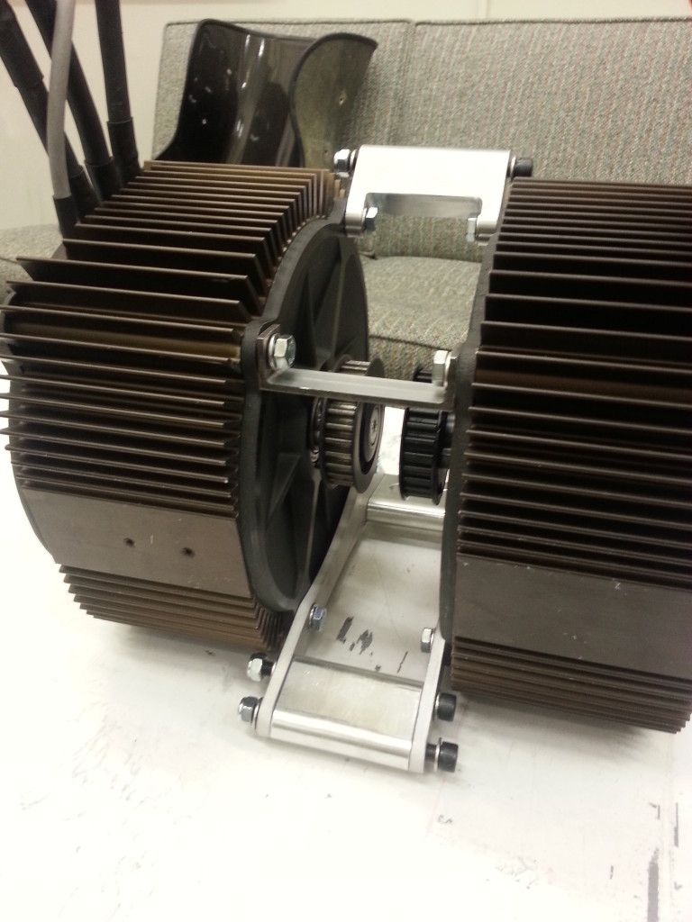
The two Zero 75-7 motors are mounted face-to-face, and hard-mounted directly to tabs from the chassis.


