FE1 Cell Stacks
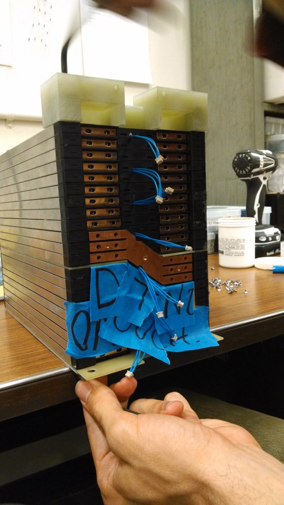
The battery is made of 20AH LiIon-NCM cells from EIG. EIG’s “cassette” style mounting system is employed. Each sub-pack Cell Stack is made up of 21 cells with a UL94-V0 rated sheet of FR4 between two sets of cells to allow the FSAE rules to be satisfied. The cells we used had been previously built into a “2p” pack with busbars which paralleled groups of two cells, however we designed a 3p battery pack so we had new paralleling busbars water-jet cut out of copper plate.
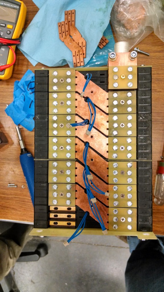
The busbars are bolted to the cell tabs using hex-head M3 screws which were torqued with a torque screwdriver. The threaded hole in the middle of the busbar is to allow attachment of the cell-by-cell voltage tap board.
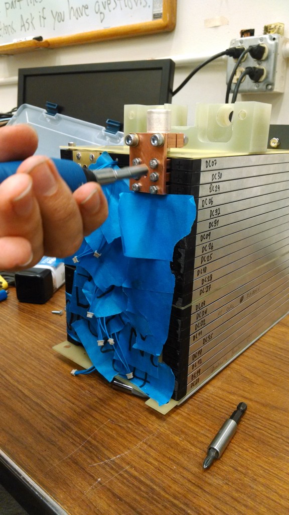
For these one-off battery assembly jobs I find blue-tape to be helpful protection against accidental short circuit.
And finally the main positive busbar can be installed with the Radsok sleeve for connection to the other packs or lid assembly. One (of several) negative aspects of this style of interlocking cell packaging is that the entire pack must be un-built and all busbars removed if a cell or cassette near the bottom needs to be replaced. This happened once or twice during assembly when the nut captured in the cassette stripped or cross-threaded. In retrospect I am not a fan of this style of cell termination.
And then, without the insulation tape, with all of the nut-locking plates installed (also to comply with FSAE rules)
Now, with the installation of the cell-tap PC board. There is a MiniFit Jr connector at the top which connects to the BMS harness. The temperature sensor strategy is described in the ESF excerpt posted on the title page. There is 1 thermistor which is quantitatively measured by the BMS and then additional digital temperature switches which are in wired-OR configuration and will trigger an overtemp shutdown if any one of them trips.
And finally, with the insulation “front shield”, ready to install in the accumulator enclosure. Pay no attention to the mess!


