FE1 Power Electronics Assembly
In the construction of FE1 we left power electronics packaging ’till fairly late in the game, which made for a stressful time, but fortunately the product came out well. My colleague Zac really stepped up and did much of the detail design on this assembly. We realized it was a bigger challenge than we had expected to package the twin motor controllers, energy meter, DC/DC converter, low-voltage interfacing equipment, plus a pair of contactors and a pair of large class T fuses which aren’t in the following diagram:
Again, just like the battery pack packaging, all of the components are mounted to the bottom side of the top plate. This made for easy entry and exit of the connectors and allowed the motor controller heatsinks to face upwards and be better exposed than if they were on the bottom of the box. It also meant that in the case of water intrusion it is guaranteed that no components will end up sitting in water.
The first test fit of the un-riveted battery pack and power electronics enclosure in the chassis is a smashing success– it is fabulous when the fit you saw in CAD manifests in real life!
Soon, time to begin final assembly, starting from the bottom up with bolting the controllers to the heatsinks, and the heatsinks to the box lid. Just like with the battery pack lid, all the work to this assembly is done with it upside-down from its eventual orientation in the vehicle.
Then, filling in the other parts which are bolted or screwed to the lid.
Zac designed a mess of flying busbars to connect the motor controllers to the output J-boxes on the lid of the enclosure. We had them waterjet cut out of a large sheet of 1/8″ copper. Before bending or sleeving:
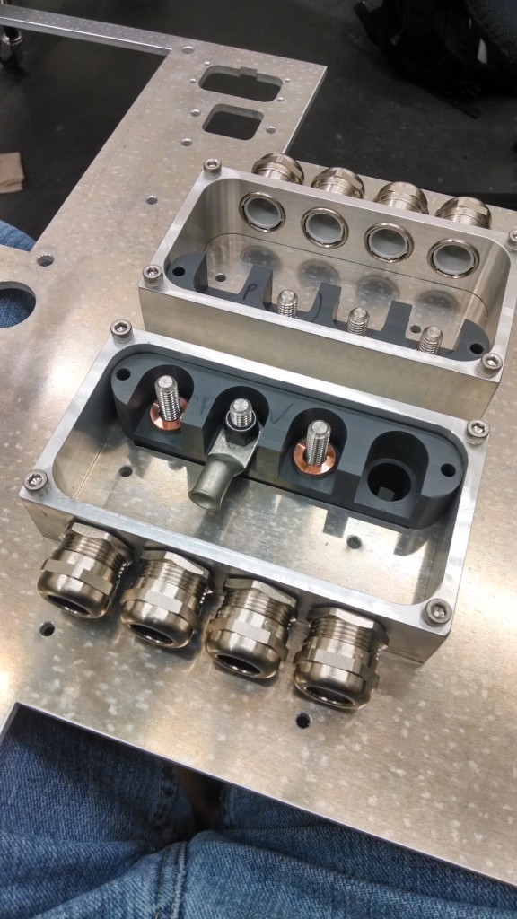
The motor connection J-boxes worked out very well as a not-quite-quick, but quick enough disconnect between the motors and controllers. Three phase leads, and commutation sensor harness. All are “tractive system wiring” with respect to the rules, since the motor controllers share logic and battery ground and the sensors are referenced to motor controller logic ground and powered from the controller’s non-isolated supply!
After hours of carefully sleeving, fitting and safety wiring the busbars, and more hours painstakingly constructing the circuitous wiring harness, the Power Electronics Enclosure is just about ready to go into the vehicle! The busbar ziptied to a block of wood in the center is our designated location for the competition-supplied Energy Meter. The judges were able to connect to it via WiFi through the aluminum box!
Because these Sevcon material handling controllers are based on a low-voltage architecture and share logic ground with the battery ground, we had to construct circuits to isolate all of the digital (KSI, enable, contactor) signals and analog (throttle) signals from our vehicle harness in order to meet the FSAE rules. These PC boards housed that hardware along with our DC-Link capacitance fast-discharge circuit.


